Battery Life Isn't Magic —
It's Engineering
Actual power optimisation techniques we used on the Smart Golf Ball and Sports Wearable projects: sleep modes, interrupt-driven wake, radio duty cycling, peripheral power gating, and DMA. With real Nordic Power Profiler measurements.
Every embedded project we take on at DigitalMonk starts with the same two questions before we ever touch a schematic: how long does this have to run, and what's the coin cell budget? For the Smart Golf Ball and the Sports Wearable, those questions defined every architectural decision from MCU selection through to firmware scheduling strategy. This post is a teardown of exactly what we did — not a tutorial on nRF SDK APIs, but the reasoning, the measurements, and the trade-offs we actually lived through. Both projects used nRF5 SDK; if you're evaluating the SDK choice for a new nRF design, our nRF5 SDK vs nRF Connect SDK comparison covers that separately.
Two Devices, Two Very Different Power Envelopes
Before we dive into techniques, it's worth establishing why these two devices needed such different strategies despite both running on nRF52840.
The Golf Ball is in deep sleep for more than 99.9 % of its life. It needs to detect a strike event, record IMU data for the ball's flight arc, transmit via BLE, and go back to sleep — all in a few hundred milliseconds. The Wearable is the opposite: it needs to sustain 400 Hz IMU sampling across a full sprint or training session, with continuous BLE connection to a phone app. Two completely different firmware architectures, same silicon.
| Parameter | Smart Golf Ball | Sports Wearable |
|---|---|---|
| MCU | nRF52840 | nRF52840 |
| IMU | LSM6DSO (SPI) | ICM-42688-P (SPI) |
| Radio usage | Burst on event | Continuous connection |
| Target sleep current | < 5 µA | ~80 µA (connected standby) |
| Peak active current | ~9 mA (Tx burst) | ~12 mA (IMU + BLE) |
| Primary wake source | IMU DRDY / tap interrupt | Timer + BLE event |
| Battery life achieved | 18+ months | 4.5 hours active |
Sleep Modes on nRF52840: What Actually Matters
The nRF52840 ARM Cortex-M4 has three relevant low-power states. The SDK wraps these, but knowing what happens in hardware tells you exactly why certain choices crush battery life.
| State | CPU | RAM | Peripherals | Typical Current | Wake Latency |
|---|---|---|---|---|---|
| WFI (Wait for Interrupt) | Halted | Retained | Active (clocked) | 1.5–3 mA | < 1 µs |
| System ON — No CPU activity | Off | Retained | Selectively on | ~1.5 µA + peripherals | ~6 µs |
| System OFF | Off | Lost (GPREGRET only) | All off | ~0.4 µA | Pin/NFC wake → reset |
For the Golf Ball, we spend the vast majority of time in System ON with the CPU off, not System OFF. This sounds counterintuitive — System OFF is lower current on paper. The reason: waking from System OFF is effectively a cold boot. SoftDevice re-initialises, BLE advertising restarts, and you lose ~20 ms and ~6 mA·ms of charge on every wake. At strike frequency (maybe 50–100 strikes per round), that overhead is significant. System ON keeps the BLE stack warm in SoftDevice and lets us wake via IMU interrupt, capture data, and burst-transmit within ~140 ms — then return to sleep.
On the Golf Ball, System OFF would have saved ~1.1 µA in absolute sleep current but cost us ~18 µA average when accounting for cold-boot overhead at realistic strike frequency. System ON sleep won on every metric that mattered.
Calling sd_app_evt_wait() Correctly
In SoftDevice builds, you cannot call __WFE() directly — you use sd_app_evt_wait(). The SoftDevice schedules BLE events, releases control, and your application main loop calls this. What kills power here is spin-polling on a flag before calling wait. We saw this in one early build of the wearable scheduler: a 2-second interval timer flag was being polled with a while(!flag) loop. The nRF never entered low-power because the CPU was always executing. A simple callback-into-flag combined with sd_app_evt_wait() in the main loop dropped current by 780 µA in connected standby.
/* WRONG — CPU never sleeps */
while (!m_data_ready_flag) /* spin */
process_imu_data();

/* CORRECT — CPU enters WFI via SoftDevice */
while (true) {
    if (m_data_ready_flag) {
        m_data_ready_flag = false;
        process_imu_data();
    }
    uint32_t err = sd_app_evt_wait();
    APP_ERROR_CHECK(err);
}
Interrupt-Driven Wake: No Polling, Ever
On both devices, zero CPU cycles are spent polling sensor state. Everything is interrupt-driven. The nRF52840's GPIOTE peripheral is key here — it can detect edge transitions on any pin without waking the CPU, and it has a GPIOTE→PPI→SAADC/SPI shortcut path that can trigger peripheral DMA without any CPU involvement at all.
On the Golf Ball, the LSM6DSO's INT1 pin fires on two conditions: a significant tap/impact event (to detect a strike), and a data-ready interrupt when new IMU samples are available during a recording window. We configure two separate interrupt modes depending on state:
Deep Sleep Mode — Tap Detection Only
INT1 configured for single/double-tap interrupt via TAP_CFG1 and WAKE_UP_THS registers. Only the IMU tap engine is running, consuming ~7 µA on the sensor side. GPIOTE configured as a sense interrupt on the nRF — CPU stays off, only GPIOTE logic watches the pin.
Strike Detected — Mode Switch
GPIOTE interrupt fires. ISR runs in under 2 µs: sets a flag, reconfigures INT1 to DRDY mode via SPI, starts the recording timer. Returns immediately — no blocking in the ISR.
Recording Window — DRDY Interrupt at 1666 Hz
Each IMU data-ready pulse triggers a GPIOTE interrupt. ISR initiates an SPI DMA transaction (SPIM, not SPIS) to pull 12 bytes of accel+gyro data into a ring buffer. CPU returns to WFI between each DMA completion.
Recording Complete — BLE Burst Tx
After 80 ms of data captured (±133 samples), flag is set in main loop. BLE notifications sent over connection (pre-established with phone or queued for next advertisement). Return to deep sleep.
First cut of the Golf Ball ISR called nrf_drv_spi_transfer() directly inside the interrupt handler. This caused SPI to block while in ISR context — creating a 240 µs window where the nRF could not service BLE SoftDevice events. On a 1666 Hz DRDY, that's 400 µs of blocked time every millisecond. Fixed by posting a flag from ISR, initiating SPI in main loop context after sd_app_evt_wait() returns.
/* ISR — must be fast, no blocking */
static void imu_int1_handler(nrf_drv_gpiote_pin_t pin, nrf_gpiote_polarity_t action)
{
    /* Single atomic write — no SPI, no delays */
    m_imu_drdy = true;
    /* If needed, signal app scheduler */
    app_sched_event_put(NULL, 0, imu_fetch_handler);
}

/* App scheduler callback — runs in main loop context */
static void imu_fetch_handler(void *p_ctx, uint16_t size)
{
    /* Initiate DMA SPI — non-blocking, returns immediately */
    nrf_drv_spi_transfer( &m_spi, m_tx_buf, 1, m_rx_buf, 13);
    /* spi_event_handler fires on DMA complete */
}
BLE Radio Duty Cycling: The Biggest Lever
The radio is by far the heaviest consumer on the nRF52840 — 5.3 mA in TX at 0 dBm, 4.6 mA in RX. Every millisecond of unnecessary radio-on time directly eats into your battery. On both devices we attacked this differently.
Golf Ball — Advertising Interval Strategy
The Golf Ball does not maintain a persistent BLE connection. Instead, after a strike event, it enters a fast-advertising window (100 ms interval) for 5 seconds, then drops to a slow-advertising window (1 s interval) for 25 seconds, then goes back to sleep if no connection is made. This is the standard tiered approach, but the numbers matter enormously at CR2032 scale.
| Advertising Mode | Interval | Adv Packet Duration | Duty Cycle | Avg Current |
|---|---|---|---|---|
| Fast (post-strike) | 100 ms | ~1.5 ms | 1.5 % | ~88 µA |
| Slow (timeout fallback) | 1000 ms | ~1.5 ms | 0.15 % | ~8.8 µA |
| Connected (data transfer) | 20 ms conn interval | varies | ~5–8 % | ~380 µA |
| Deep sleep (no radio) | — | — | 0 % | ~3.8 µA |
The key architectural insight: we do not advertise at all when no strike has occurred. The ball is completely silent. A phone app that wants to find the ball must be patient — it only shows up after a strike. This was a UX decision as much as a power decision, and it's why the 18-month battery life is achievable.
Wearable — Connection Parameter Negotiation
The Sports Wearable maintains a continuous connection during a training session. The critical parameter here is the BLE connection interval. A short interval means more radio wake-ups; a long interval increases latency. We targeted a 20 ms connection interval during active recording (needed for 400 Hz IMU → real-time display on phone) and negotiated a 500 ms interval during idle standby between sets.
Connection interval negotiation happens via sd_ble_gap_conn_param_update(). The phone can reject the request and suggest different values — so your firmware needs to handle the negotiation callback and work with whatever the central offers. On iOS this is particularly important because iOS BLE stack has its own preferences and will often push back on aggressive intervals below 15 ms.
Peripheral Power Gating: Don't Leave the Lights On
Both devices have peripherals that consume power even in standby if you don't explicitly control their power rails. On the Golf Ball, the LSM6DSO has a sleep current of ~7 µA in its own low-power mode — but that's still almost double the nRF's sleep current. On the Wearable, the ICM-42688-P in low-noise mode draws ~0.8 mA just sitting there.
Both devices have a dedicated load switch (Diodes Inc. AP2281) on the sensor power rail, controlled by a GPIO from the nRF. This lets us completely gate power to the IMU and any other sensors without relying on the sensor's own standby mode — which many IMU vendors implement inconsistently across silicon revisions.
Power gating has a cost: when you bring a sensor back up, you need to wait for its startup time (typically 5–20 ms for IMUs), re-initialise its configuration over SPI, and verify its WHO_AM_I register before trusting data. On the Golf Ball we added a 12 ms delay after power gating ON — this was validated with a logic analyser confirming stable SPI comms before the first DRDY fires. Skip this and you'll occasionally get corrupted first samples.
/* GPIO controlling AP2281 load switch enable pin */
#define IMU_PWR_EN_PIN NRF_GPIO_PIN_MAP(0, 17)

void imu_power_on(void)
{
    nrf_gpio_pin_set( IMU_PWR_EN_PIN);
    /* Wait for LDO stabilisation + IMU boot */
    nrf_delay_ms(12);
    /* Re-configure all registers — config is lost on power cycle */
    imu_configure();
}

void imu_power_off(void)
{
    /* Disable interrupts before gating to avoid phantom GPIOTE fires */
    nrf_drv_gpiote_in_event_disable( IMU_INT1_PIN);
    nrf_gpio_pin_clear( IMU_PWR_EN_PIN);
}

/* In deep sleep routine */
void enter_deep_sleep(void)
{
    imu_power_off(); /* Kill sensor rail */
    spi_uninit(); /* Release SPI peripheral */
    led_power_off(); /* Gate LED driver */
    /* Re-enable tap-wake pin via GPIOTE sense */
    configure_tap_wake_gpio();
    /* Enter System ON sleep — CPU off, GPIOTE watching */
    sd_app_evt_wait();
}
One detail that burned us on the Wearable: we were uninitialising the SPI peripheral when going to standby between sets, which is correct. But we left the SPI pins in their default GPIO state (floating inputs). Floating inputs on the MOSI and SCK lines were creating small leakage currents through the IMU's ESD protection diodes — visible on Power Profiler as ~22 µA unexplained floor current. Fixing this to drive the SPI lines low before ungating the peripheral brought standby down to expected levels.
SPIM DMA: CPU-Free Data Acquisition
At 400 Hz IMU sampling on the Wearable, the CPU would be interrupted 400 times per second just to service SPI reads if we used the blocking SPI driver. Each read pulls 14 bytes (accel + gyro, 16-bit each + status). That's 400 × 14 = 5,600 bytes per second — trivial bandwidth, but at 400 interrupts/sec the context-switch overhead is real and the CPU is never deep-sleeping for more than 2.5 ms.
The solution is the nRF52840's SPIM peripheral with Easy DMA. The SPIM DMA engine can transfer a burst of bytes to/from RAM while the CPU remains in WFI. The full flow:
GPIOTE → PPI → SPIM START shortcut
Configure a PPI channel: on the IMU INT1 rising edge, the SPIM.TASKS_START event fires automatically. No ISR, no CPU wake. The DMA burst begins purely in hardware.
SPIM DMA transfer — 14 bytes from IMU registers
SPIM drives SCK, MOSI, and CS. 14 bytes land in m_rx_buf in RAM. CPU stays in WFI. This takes ~14 µs at 8 MHz SPI.
SPIM END event → interrupt
Only now does the CPU wake. ISR runs in ~1 µs: copies buffer to ring, increments write pointer, returns to WFI. All signal processing happens at the end of a capture window, not sample-by-sample.
This PPI shortcut approach means that for a 400 Hz IMU, the CPU wakes only 400 times per second for ~1 µs each — 400 µs total CPU-on time per second dedicated to DMA bookkeeping. Without this pattern, you'd be spending 3–5 ms per second in ISR overhead alone, plus the current spike of coming out of WFI 400 times.
static void configure_ppi_imu_shortcut(void)
{
    uint32_t gpiote_event_addr, spim_task_addr;
    nrf_ppi_channel_t ppi_ch;

    /* Get GPIOTE event address for IMU INT1 pin */
    gpiote_event_addr = nrf_drv_gpiote_in_event_addr_get( IMU_INT1_PIN);

    /* Get SPIM START task address */
    spim_task_addr = nrf_drv_spi_start_task_get(&m_spim);

    /* Allocate and configure PPI channel */
    nrf_drv_ppi_channel_alloc(&ppi_ch);
    nrf_drv_ppi_channel_assign( ppi_ch, gpiote_event_addr, spim_task_addr);
    nrf_drv_ppi_channel_enable(ppi_ch);
    /* DMA now starts on every IMU interrupt — no CPU needed */
}

/* Only fires after DMA complete — bookkeeping only */
static void spim_event_handler(nrf_drv_spi_evt_t const *p_event, void *p_context)
{
    if (p_event->type == NRF_DRV_SPI_EVENT_DONE) {
        ring_buf_push( &m_imu_ring, m_rx_buf, 14);
    }
}
Power Profiler Methodology: Measure Before You Optimise
Every number in this post was measured with the Nordic Power Profiler Kit II (PPK2), not estimated from datasheets. Datasheet numbers are best-case values in ideal conditions with everything else off. Real devices have voltage regulators with quiescent currents, floating pins, SoftDevice overhead, and partial peripheral initialisation — none of which appears in the datasheet.
Never quote a power number that didn't come from a PPK2 measurement of your actual board. Every single project where we've trusted datasheet figures alone has produced a device that misses battery target on first hardware spin.
PPK2 Setup for nRF52840 Targets
| Scenario | PPK2 Mode | V_SOURCE | Sampling Rate | Window |
|---|---|---|---|---|
| Deep sleep verification | Source meter | 3.0 V (Golf Ball) / 3.7 V (Wearable) | 100 kHz | 10 s |
| Strike event profile | Source meter | 3.0 V | 1 MHz | 500 ms |
| BLE connection current | Source meter | 3.7 V | 100 kHz | 5 s |
| Average session current | Source meter + Ampere-hour | 3.7 V | 100 kHz | 30 min |
For the Golf Ball, the critical measurement is the average current over a realistic usage session — not just the sleep floor. We simulate a round of golf (70 strikes over 4 hours) by scripting the IMU tap detector with a signal generator and recording the total charge consumed via PPK2's coulomb-counting mode. Divide mAh consumed by the CR2032 nominal capacity (220 mAh), multiply by session frequency, and you get a real battery life estimate, not a theoretical one.
Working on a battery-constrained nRF device?
Our Nordic nRF development team has shipped products from CR2032-powered sensors to multi-sensor wearables — all measured, validated, and production-ready.
The Full Optimisation Playbook: What We Apply on Every Build
Below is the complete checklist we run through on every nRF project before declaring a battery-life target. The order matters — tackle the biggest current contributors first, measure after every change.
| # | Technique | Typical Saving | Golf Ball | Wearable | Effort |
|---|---|---|---|---|---|
| 1 | Correct sleep loop (sd_app_evt_wait, no spin) | 500 µA – 2 mA | ✓ | ✓ | Low |
| 2 | Radio duty cycling (advertising intervals, conn param) | 50–800 µA avg | ✓ | ✓ | Medium |
| 3 | Peripheral power gating (load switch, not standby mode) | 7–800 µA | ✓ | ✓ | Medium |
| 4 | SPI pin state on sleep (drive low, no float) | 10–30 µA | ✓ | ✓ | Low |
| 5 | Interrupt-driven wake (no polling loops) | 200 µA – 3 mA | ✓ | ✓ | Medium |
| 6 | SPIM DMA + PPI shortcut (CPU-free data capture) | 50–200 µA | ✓ | ✓ | High |
| 7 | TX power tuning (reduce from 0 dBm where RSSI allows) | 0.5–1.5 mA peak | ✓ | — | Low |
| 8 | DC/DC regulator enable (NRF_POWER_DCDCEN) | 20–50 µA active | ✓ | ✓ | Low |
| 9 | Clock source (LFRC vs LFXO vs synthesised) | 0.1–0.9 µA | — | ✓ | Low |
| 10 | Validate with PPK2 (measure every stage, no estimating) | Prevents all regressions | ✓ | ✓ | Low |
One number that always surprises clients
Enabling the internal DC/DC regulator on the nRF52840 with (or Zephyr's CONFIG_SOC_DCDC_NRF52X=y) typically saves 20–50 µA in active mode for almost zero engineering effort. It's always the first thing we add. On a coin-cell device running 12 hours/day, that alone adds months to battery life.
Both Projects, Full Case Studies
The techniques described in this post were developed and validated across two real shipped products. If you want to see the full hardware stack, PCB design, and firmware architecture behind these numbers:
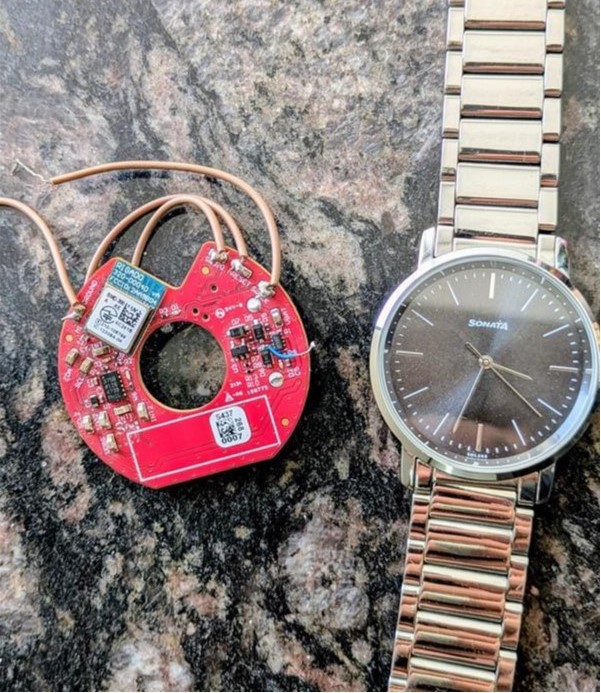 Case Study · Golf
Smart Golf Ball — nRF52840, BLE Mesh, Custom PCB, CR2032
IMU-based ball flight tracking with 18-month battery life. Full PCB layout, antenna design, and BLE mesh network for multi-ball tournaments.
Read case study →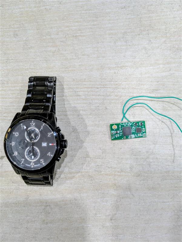 Case Study · Sports Tech
Sports Wearable — Sprint & Jump Analyser, nRF52840, IMU, Real-Time BLE
400 Hz IMU sampling, DMA-driven acquisition, real-time BLE to iOS/Android companion app for sprint velocity and jump height tracking.
Read case study →If your project has similar constraints — a coin cell budget, a demanding sampling rate, or a hostile RF environment — reach out to our Nordic nRF development team. We have the hardware lab, the PPK2 on the bench, and the firmware scar tissue to make it work.