ESP32 Model Railway Track Controller: A Case Study
How we designed a custom ESP32 servo controller to switch 24 track points on a large home layout — Wi-Fi operated, per-point calibration, delivered in under three weeks.


Project Overview
A private model railway enthusiast came to us with a large home layout and a clear problem: he wanted to switch the track points electronically, from a web app, without being tethered to the track. Off-the-shelf DCC controllers didn't fit what he needed. We designed a custom ESP32-based controller board that drives servo motors at each point, built the Node.js API layer, and wrote the ESP32 firmware — boards delivered and working within three weeks.
The Challenge
Switching track points — the movable rails that direct a train left or right at a junction — is one of the oldest problems in model railways. On a small layout, doing it by hand is fine. On a large layout with 24 points spread across the room, it is not. You either need to walk to each point or you need a control system.
Traditional DCC (Digital Command Control) systems handle point switching as one of many features in a broad, standards-based ecosystem. For this client, that ecosystem came with more complexity and cost than the application justified. He wanted something simpler: a dedicated controller for the points, operated from a web app on his phone or tablet, with no proprietary hardware dongle or command station required.
The requirements were concrete:
- ◆Electronic control of 24 track points across a large layout
- ◆Remote operation via a web app — no physical button panel
- ◆Precise, repeatable point movement — no over-rotation, no straining the mechanism
- ◆Per-point calibration: each servo tuned individually to its own throw
- ◆Scalable — backup boards, and room to add more points later
- ◆Clean power: 12 V via USB-C, no bespoke power supplies
The core engineering challenge was not just driving servos — it was driving them accurately. A servo that moves too far breaks the point linkage or damages the motor. One that doesn't move far enough leaves the point mid-throw, which derails trains. Every point on the layout needed individual calibration, and the system had to remember and apply those settings reliably every time.
The Solution: Hardware
Custom ESP32 PCB — Eight Servo Channels Per Board
We designed a custom PCB built around the ESP32 — a proven, capable microcontroller with integrated Wi-Fi that our ESP32 developers have shipped across multiple product types. The board provides eight independent servo output channels, each with its own header for signal, power, and ground. Three boards cover the 24-point layout, each managing a physical zone. Additional boards were supplied for backup and future expansion.
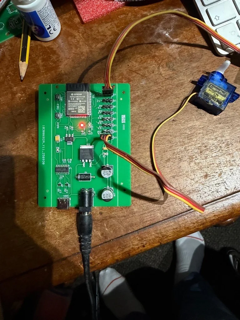
Power comes in at 12 V over USB-C — a modern, reliable connector that the client can source anywhere. The board handles power distribution to the servo outputs, with the ESP32 running on regulated 3.3 V from an onboard converter. The USB-C power input was a deliberate choice: no proprietary barrel jacks, no hunting for the right adapter.
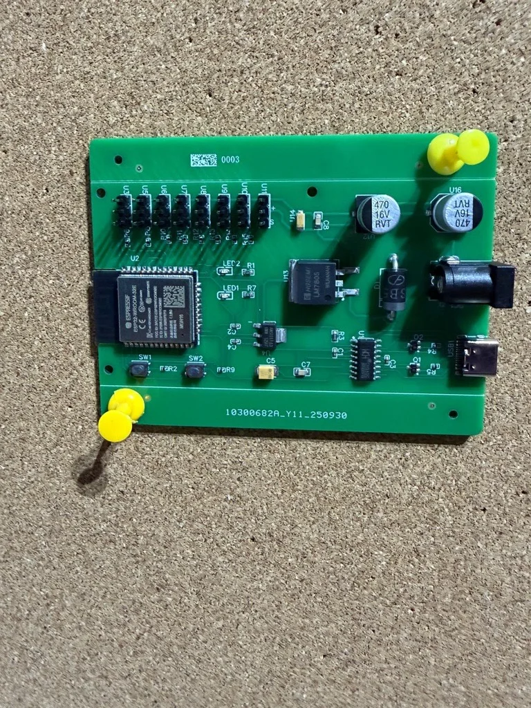
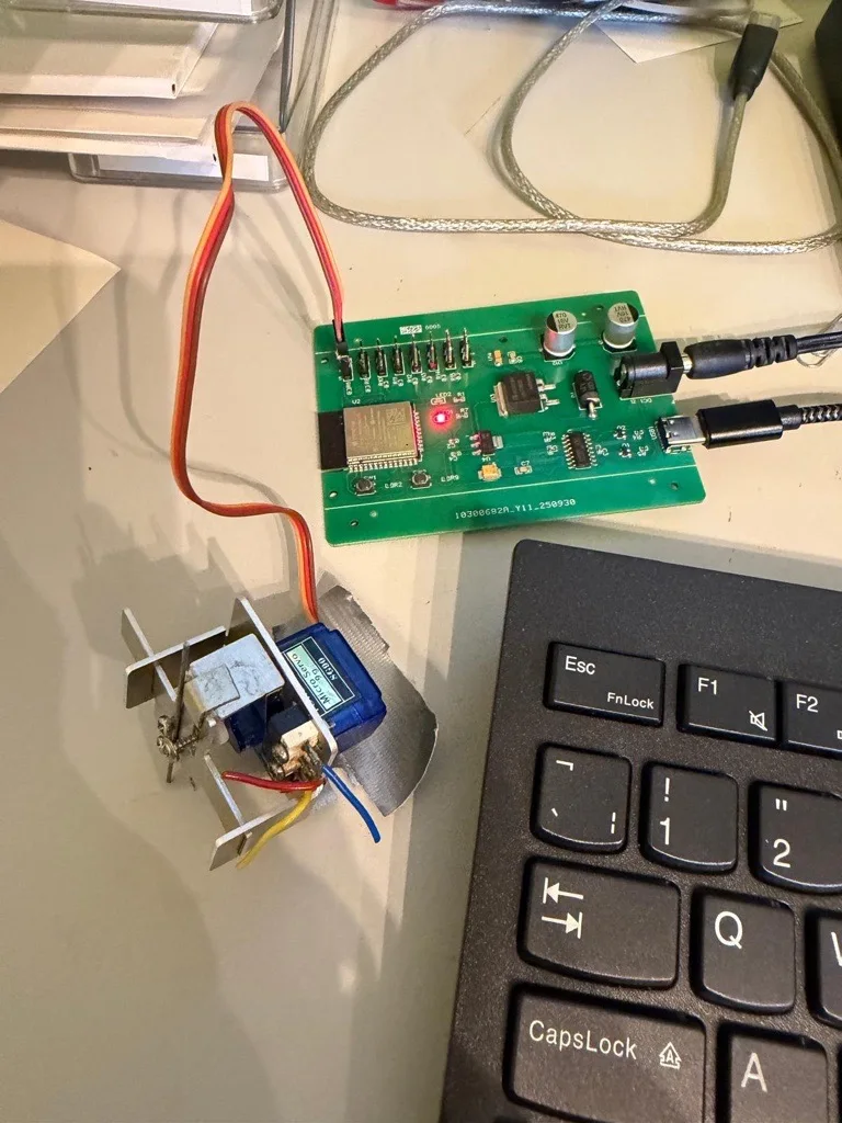
Each servo connects directly to its channel header. The board design keeps servo signal lines clean and short, with the ESP32 generating PWM output on each channel independently. This is not a dev-board stack held together with jumper wires — it is a purpose-designed PCB for this specific application, built to sit inside the layout and run reliably for years.
The Solution: Firmware, Calibration & Control
ESP32 Firmware and Wi-Fi Communication
The ESP32 on each board runs firmware we wrote specifically for this application. On startup, the board connects to the layout's Wi-Fi network and begins listening for commands from the API layer. When a point command arrives — throw point 3 to diverging — the firmware drives the corresponding servo channel to the configured angle and holds it. There is no manual reset, no reboot cycle. Commands arrive and the board acts on them immediately.
Node.js API Layer
We built the Node.js API layer that sits between the web application and the ESP32 boards. The API receives commands from the web app, resolves which board manages the requested point, and forwards the command to that board over Wi-Fi. The client's web front-end — which he handled on his side — talks only to the API. The API handles all the board-addressing logic, keeping the front-end simple and the boards focused on servo execution.
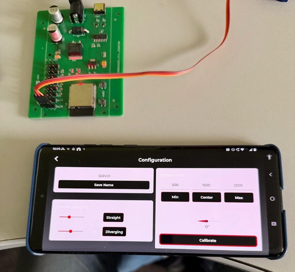
Per-Point Calibration: The Key Engineering Focus
The part of this project that required the most care was servo calibration. Every track point on the layout is slightly different — the linkage geometry, the stiffness of the tiebar, the distance between the servo mount and the point blade. A single global angle setting would not work.
The system gives each servo output its own configuration:
- 1Output name
Each servo channel is named — "Platform 1 entry", "Goods yard throat" — so the web app displays meaningful labels rather than channel numbers.
- 2Throw angles: straight and diverging
The angle for each position is set independently. Straight does not have to be the same number of degrees as diverging — the calibration reflects the actual mechanical geometry at each point.
- 3Min / centre / max limits
Servo travel is bounded with explicit minimum, centre, and maximum limits. The firmware will not command the servo outside these bounds regardless of what the API sends, protecting both the servo and the point mechanism from over-rotation.
This throw-limiting behaviour was the most important safety constraint in the firmware. A servo that over-rotates can strip its gears, bend the linkage, or crack a plastic point tiebar. With per-servo limits enforced in firmware, those failure modes are not possible regardless of what command is sent.
Why the Engineering Focus Mattered
Model railway point mechanisms are not forgiving. The tolerances in a plastic or metal tiebar are small, and a servo that applies force beyond the throw it needs will eventually fail something — the linkage, the point blade, or the servo itself. Getting the calibration right is not a nice-to-have; it is what makes the system usable long-term.
By building calibration into the firmware — not just into the web app as a display setting — we made the protection persistent and hardware-enforced. Even if a rogue API call somehow sent an out-of-range angle, the firmware would clamp it. That distinction matters in a system that will run unattended, across a layout the owner has spent years building.
The same precision that makes the system safe also makes it repeatable. Each point throws to exactly the same position every time the command is given. On a busy layout with multiple trains running, reliable, consistent point operation is the difference between a session and a derailment.
The Result
Working boards delivered in approximately 16–18 days. Custom PCB fabrication is part of that timeline — fabrication lead time is a fixed constraint in any custom hardware project, and we worked around it by running firmware and API development in parallel. By the time the boards arrived from the fab, the firmware was ready to flash and the API was ready to test.
The client's 24 track points are now controlled from a web app. Each point is named, calibrated, and reachable from anywhere on the Wi-Fi network — phone, tablet, or desktop. Backup boards are on hand for any board-level issue, and expansion boards are ready if the layout grows.
The system works the way a purpose-built controller should: you press a button, the point moves to the right position, and it stays there. No DCC command station, no proprietary handheld, no complex setup. A custom board, custom firmware, and a clean API — doing exactly the job it was built for.
Why DigitalMonk
This project needed three things done well and done in parallel: a custom PCB, firmware that handles servo calibration correctly, and a Node.js API that routes commands to the right board. When all of that sits under one roof, the timeline compresses. Hardware decisions feed directly into firmware choices; API design reflects what the firmware actually does. There are no handoffs, no version mismatches, no waiting on another contractor.
We take on applications like this — specific, niche, not covered by any off-the-shelf product — as a matter of course. Model railway controllers, custom industrial panels, servo-driven automation rigs: the underlying capability is the same. If the application calls for a custom ESP32 board with precise motor control and a clean API, our ESP32 developers have done it before.
For a broader view of what we build as an IoT development company, or to see the range of our embedded development services, those pages have the detail. We work with clients across India, the UK, and the US on fixed-scope hardware builds and longer-term embedded team engagements.
If you want to see another example of a custom ESP32 project — a sensor device rather than a controller — take a look at our custom air quality monitor case study. Different application, same approach: purpose-designed PCB, in-house firmware, working hardware delivered fast.
Custom PCB Design
Purpose-built boards for your application — not dev-board stacks, not off-the-shelf modules rebranded
Embedded Firmware
ESP32, STM32, or whatever the job calls for — firmware that handles edge cases and runs reliably in the field
API & Connectivity
Node.js APIs, Wi-Fi integration, and control interfaces built alongside the hardware — not bolted on after
Fast Delivery
Custom hardware in weeks, not months — possible only when PCB, firmware, and software are all in-house
Hire an ESP32 Developer — DigitalMonk
Custom boards, firmware, and APIs — from model railway controllers to industrial automation. Tell us what you need to build.
Frequently Asked Questions
Have a Custom Control Project?
Model railway, automation rig, or something nobody's built before — we design the board, write the firmware and APIs, and ship working hardware. Tell us what you're building.