From Breadboard to PCB: The Modern Prototyping Workflow Explained
In hardware product development, one moment defines whether your idea becomes a real product—or dies in endless iteration:
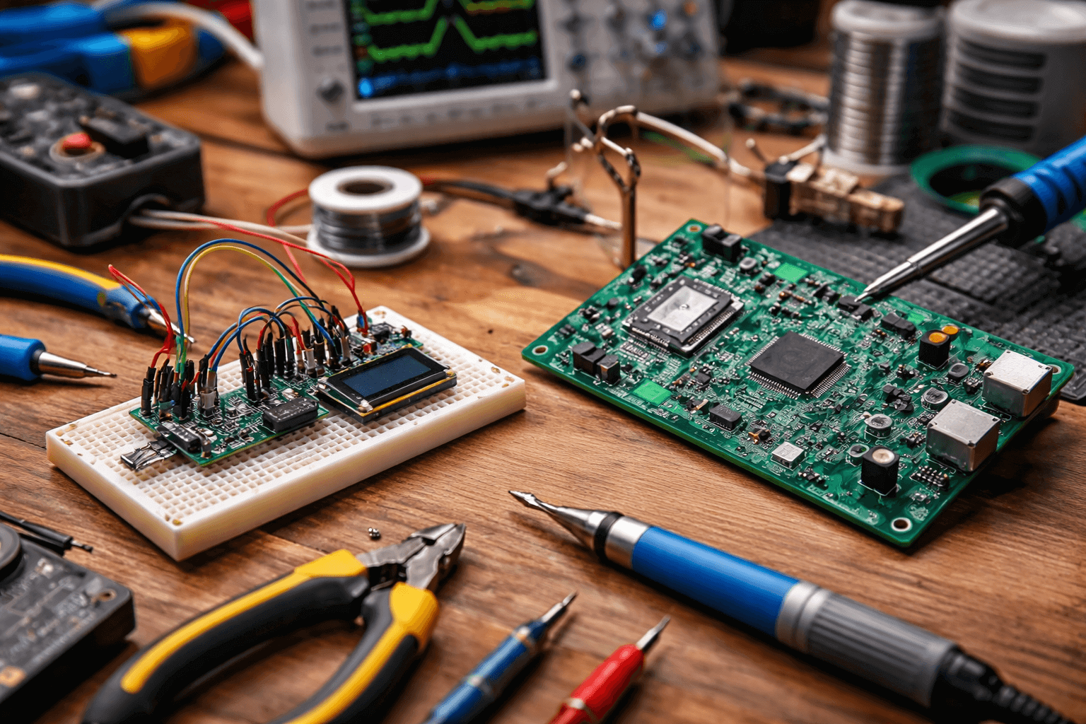
👉 The transition from breadboard prototype to a production-ready PCB. Many founders and engineers can get an idea working on a breadboard using Arduino, ESP32, or Raspberry Pi. But moving from that fragile, wire-filled setup to a reliable PCB is where most hardware projects slow down, overspend, or fail.
In 2026, the prototyping workflow has evolved significantly. New tools, better design practices, and tighter integration between hardware, firmware, and manufacturing have made it faster—but also less forgiving for mistakes. This guide explains the modern, real-world workflow from breadboard to PCB, helping you avoid common traps and build electronics that actually scale.
Building an IoT product that needs to scale?
Why Breadboards Still Matter (Even in 2026)
Despite all the advances in PCB tools and simulation software, breadboards are still the starting point for most hardware ideas. A breadboard allows you to:
Test circuit logic quickly
Experiment with sensors, displays, and communication modules
Validate pin mappings and voltage levels
Change components without redesigning hardware
For early-stage prototyping, breadboards answer one key question:
👉 “Does this circuit concept actually work?”
Typical Breadboard Use Cases
Sensor testing (temperature, motion, pressure)
MCU pin validation
Power supply experiments
Communication testing (I2C, SPI, UART, BLE, Wi-Fi)
Breadboards are about speed and learning, not reliability.
The Limitations of Breadboard Prototypes
While breadboards are useful for early validation, they possess inherent physical limitations that impede professional product development.
Key Technical Limitations
⚡
Loose connections and signal noise
🔋
Poor power integrity
📡
No EMI/EMC control
🛠️
Impossible to test real-world reliability
🔄
Not scalable or repeatable
🔍
Difficult to debug complex systems
Critical Alert: A circuit that works on a breadboard may fail completely when introducing:
Higher frequencies
Wireless communication
Power-sensitive components
Long runtimes
Breadboard success ≠ Product readiness.
The Modern Prototyping Philosophy (2026)
In 2026, smart teams don’t jump directly from breadboard to final PCB. Instead, they follow a progressive prototyping workflow:
At this stage, clarity matters more than cleanliness.
02
Step 2: Schematic Design – The Real Transition
Once your breadboard logic works, the next step is schematic capture. This turns physical wiring into an engineering document.
Why It Is Critical
Forces systematic thinking
Reveals missing components
Makes power design explicit
Enables collaboration and review
Foundation for PCB layout
Modern Tools (2026)
KiCadAltium DesignerEasyEDAFusion Electronics
Key Focus Areas
Power regulation & protection
Decoupling capacitors
Pull-up / pull-down resistors
Clock sources & Debug headers
⚠️ Founder mistake: Copying reference designs blindly without understanding them.
03
Step 3: Design for the Real World
Breadboards hide problems. PCBs expose them. Engineers must adapt designs for physical reality.
Critical Considerations
Stable power delivery
Noise-sensitive analog signals
Grounding strategy (Digital vs Analog)
Thermal behavior
Commonly Revealed Issues
Missing capacitors
Incorrect voltage rails
Weak pull-ups
Inadequate current handling
Fixing these now saves months later.
04
Step 4: PCB Layout – Where Designs Fail
Layout is not just "connecting traces." It is about physical physics.
Signal Integrity
EMI/EMC Compliance
Power Stability
Manufacturability
Layout Best Practices
Short power loops
Solid ground planes
Proper trace widths
Controlled impedance
Decoupling cap placement
Debug test points
A bad layout can break a perfect schematic.
05
Step 5: Prototype PCB Fab & Assembly
This is your first real hardware. Prototype PCBs are learning tools, not final products.
Primary Use Cases
Validate electrical design
Test firmware on real silicon
Identify layout issues
Measure power & thermal behavior
Typical Characteristics
Low quantity (5–20 boards)
Manual/Semi-automated assembly
Easy access to test points
Larger footprints for rework
At this stage, many teams start with Raspberry Pi or Arduino prototypes to validate their design logic before committing to custom PCBs. Having Raspberry Pi developers who do PCB too ensures smooth transitions — they understand both the prototyping platform AND how to port that logic to production-grade custom hardware. A practical example of this workflow is custom Raspberry Pi HAT design, where a breadboard idea with sensors or peripherals becomes a stackable, production-ready add-on board. As hardware products become smarter and more connected, the role of firmware and system-level optimization becomes critical. This is where reliable embedded software development services help bridge the gap between early prototyping and stable PCB-based products, ensuring hardware and software evolve together.
06
Step 6: Firmware Integration & Debugging
Once the PCB arrives, reality hits. Firmware and hardware must evolve together here.
Common Issues
Wrong pin mapping • Power brownouts
Boot failures • Timing issues
Noise-induced resets
Modern Debug Tools
SWD / JTAG debuggers
Logic analyzers & Oscilloscopes
Power profilers
07
Step 7: Iteration – The Most Important Step
"Almost no PCB works perfectly on the first revision. Iteration is not failure—it’s engineering."
Typical Fixes After Rev-A
Power rail adjustments
Component value changes
Layout improvements
Additional filtering
Firmware timing fixes
Good teams expect at least 2–3 PCB revisions.
08
Step 8: Design for Manufacturing (DFM)
Once reliable, focus shifts to manufacturability. This separates hobby projects from real products.