Case Study: An Arduino Uno Clock That Stays Responsive and Remembers Its Alarm
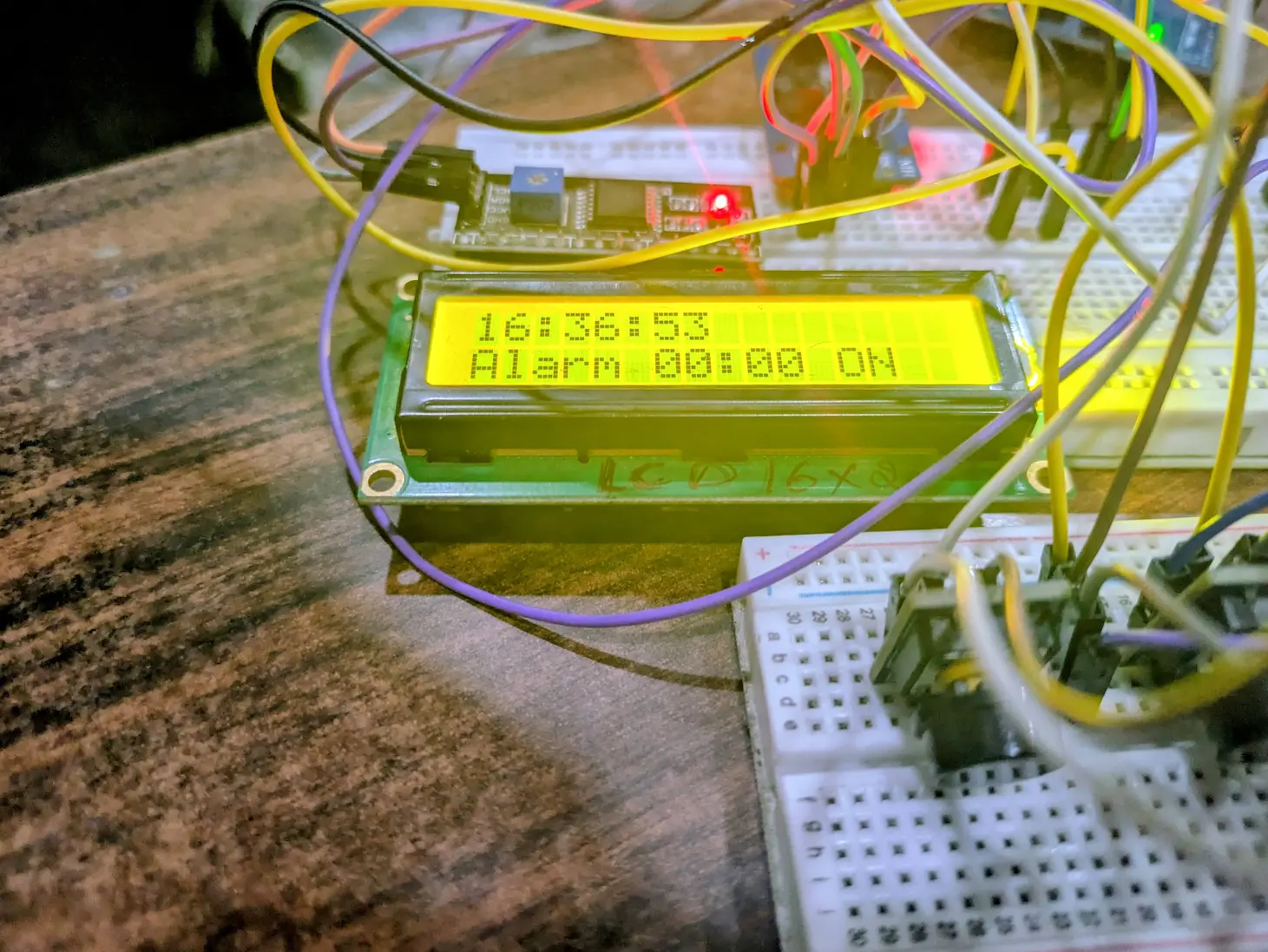
This is a DigitalMonk bench project, not a client engagement. It is a desk clock with a settable alarm, built on an Arduino Uno. A DS3231 real-time clock keeps the time, a 16x2 I2C LCD shows it, and three button modules set the time and the alarm. When the alarm time arrives, a buzzer beeps until any button is pressed or 60 seconds pass, and the alarm settings survive a power cut. It is small, but it uses the habits we rely on in production firmware: a shared bus, code that never blocks and settings that persist.


The Challenge
The goal was a simple bedside or desk clock built from common modules: show the time, let the user set the time and an alarm with three buttons, and ring at the right moment.
The details are what make it hard. A clock based on millis() drifts and forgets the time on every reset. Code that uses delay() for beeping or debouncing misses button presses. And an alarm that goes back to a default after a power cut is not much use to anyone.
Technical constraints
- Arduino Uno only: 2 KB of RAM and a single I2C port for two devices
- Off-the-shelf button modules: they output HIGH when pressed, unlike bare switches
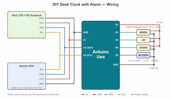
- Pin faults on the test board: D2 and D4 gave no signal, so the buttons moved to D5, D3 and D6
- No backup cell fitted: the DS3231 loses the time when power is removed
- LCD backpack: it has to be soldered to the display, and its address can be 0x27 or 0x3F
The Engineering
The clock was built in five stages, each tested on the bench before moving on. Three small throwaway sketches helped along the way: an I2C scanner, a button test and an LCD character test.
Two I2C devices on one bus
- The DS3231 RTC and the LCD's PCF8574 backpack both sit on A4 (SDA) and A5 (SCL)
- They answer at different addresses, 0x68 and 0x27, so the two never clash
- The button modules run from 5 V. At 3.3 V their output sits too close to the Uno's input threshold to be reliable
- One shared ground ties the Uno to the button breadboard
Non-blocking button handling
- Each of the three buttons is read on every pass of the loop
- A change within 40 ms of the last one is ignored, which filters contact bounce
- Only a new press is reported, so holding a button does not repeat it
- One
PRESSEDconstant switches between button modules (HIGH) and bare switches to GND (LOW)
We avoided delay() because a blocked loop is a loop that misses presses, and it would also freeze the alarm while someone is trying to silence it.
main.cpp — reading the buttons
int readButton() { // newly pressed button, or -1
  for (uint8_t i = 0; i < 3; i++) {
    bool s = digitalRead(pins[i]);
    if (s != lastState[i] && millis() - lastT[i] > 40) {
      lastT[i] = millis();
      lastState[i] = s;
      if (s == PRESSED) return i;
    }
  }
  return -1;
}A five-screen menu on a 16x2 LCD
- MODE steps through clock, set hour, set minute, alarm hour and alarm minute
- UP and DOWN change the highlighted value, and a marker shows what is being edited
- On the clock screen, UP turns the alarm on or off
- The display is redrawn every 250 ms with fixed-width lines, so no old characters are left behind
| Screen | MODE | UP | DOWN |
|---|---|---|---|
| Clock | Set hour | Alarm on/off | — |
| Set hour / minute | Next | +1 | -1 |
| Alarm hour / minute | Next (last one saves) | +1 | -1 |
| Alarm ringing | Silence | Silence | Silence |
An alarm that fires once and stops on its own
- Time is compared in minutes of the day, so the alarm fires once per matching minute and not on every loop pass
- The buzzer pattern comes from millis(): 250 ms on, 250 ms off, two beeps a second
- Any button silences it, and otherwise it stops after 60 seconds
- Buttons and the display stay responsive while the alarm rings
main.cpp — the alarm check
// Alarm fires once per matching minute
int key = now.hour() * 60 + now.minute();
if (key != almH * 60 + almM) firedKey = -1;
else if (almOn && firedKey != key) {
  ringing = true;
  firedKey = key;
  ringStart = millis();
}
if (ringing && millis() - ringStart > 60000UL)
  ringing = false;
digitalWrite(BUZZER, ringing && (millis() / 250) % 2 == 0);Settings that survive a power cut
- The alarm hour, minute and on/off state are stored in the first three EEPROM bytes
EEPROM.update()writes only when a value changes, which saves EEPROM wear- Values are range-checked at start-up, so a blank EEPROM still gives a valid alarm time
- If the RTC reports lost power, it starts from the compile time until the user sets the real time
We kept the stored data to three bytes because that is all the clock needs. The same reasoning applies to Arduino firmware written for a device people rely on: store what the user chose, validate it on the way back in, and never assume the memory is clean.
EEPROMRTClibLiquidCrystal I2CThe user sets it again every time
Same time and on/off state
The Prototype and Its Wiring
Tech Stack
The firmware is a single sketch built with PlatformIO in VS Code. It also runs in the Arduino IDE when saved as a .ino file.
| Layer | What we used | Why |
|---|---|---|
| Controller | Arduino Uno | Common, well understood, and tight enough on RAM to force clean code |
| Timekeeping | DS3231 RTC (0x68) with RTClib | Temperature-compensated, so it does not drift the way millis() does |
| Display | 16x2 LCD with PCF8574 backpack (0x27 or 0x3F), LiquidCrystal I2C | Two wires to the Uno, sharing the bus with the RTC |
| Input | Three button modules on D5, D3, D6 | Edge detection with a 40 ms debounce window |
| Alarm output | Active buzzer on D8 | Beep pattern generated from millis() |
| Persistence | Internal EEPROM, three bytes | Alarm settings that outlast a power cut |
What This Project Taught Us
Scan the bus before you debug the code
An I2C scanner confirms each device and its address in seconds. A blank LCD is often just 0x3F instead of 0x27, and solid blocks with no text point to a bad backpack joint or the contrast setting.
Never block the loop
Debouncing, beeping and redrawing all run from millis(). With no delay(), a button press is never missed, even while the alarm is ringing.
Know your input hardware
Button modules drive their output HIGH, while bare switches pull LOW. Making that one constant, and powering the modules from 5 V, removed a whole class of "buttons act strangely" bugs.
Persist what the user sets
Saving the alarm costs three bytes and a few lines, and it is the difference between a demo and a device people can rely on.
Production Reality
We want to be precise about what this is. It is a breadboard prototype that we built and tested on the bench, for our own learning and as a reference build. There was no client, no custom PCB, no enclosure and no batch. The coin cell that would keep the DS3231 running through power-off is supported by the module, but it was not fitted on the test unit, so on this build the time has to be set again after the power is removed.
Moving a design like this to production means replacing the breadboard with a board, adding the backup cell, choosing a case and defining the test steps for each unit. The firmware patterns carry over unchanged.
What This Proves
The same small set of habits sits inside most timers, loggers and button-and-display controllers: an RTC for time, a loop that never blocks and settings that persist. We apply them in embedded software beyond the breadboard and, when a prototype is ready to leave the bench, on a custom board to replace the breadboard.
Frequently Asked Questions
Why use a DS3231 RTC instead of millis() for a clock?
millis() only counts time since the last reset, so it forgets the time on every restart and drifts as it runs. The DS3231 is a dedicated, temperature-compensated real-time clock that keeps accurate time on its own. With a backup coin cell fitted it also keeps the time through a power cut.
Why avoid delay() in Arduino firmware?
delay() stops the whole loop, so button presses, display updates and the buzzer all freeze while it waits. In this clock, debouncing, beeping and redrawing all run from millis() timestamps instead, which lets a button silence the alarm at any moment.
How do I know if my I2C LCD address is 0x27 or 0x3F?
Run an I2C scanner sketch with only the LCD connected. It prints the address the backpack answers on, usually 0x27 or 0x3F. If the screen lights up but shows nothing, a wrong address is the most common cause, followed by the contrast trimmer on the backpack.
Can a DS3231 and an I2C LCD share the same Arduino pins?
Yes. I2C is a shared bus, so on an Arduino Uno both connect to A4 (SDA) and A5 (SCL). They only need different addresses, and here the DS3231 is at 0x68 and the LCD backpack at 0x27, so they never clash.
Can this breadboard prototype be turned into a real product?
The firmware patterns can, but the prototype itself is not a product. Moving to production means a custom PCB in place of the breadboard, a backup cell for the RTC, an enclosure and a test routine for each unit. We built this clock as a bench project, so those steps were not part of it.
Have a Prototype on a Breadboard?
We can turn it into reliable firmware and a custom board, ready for small-batch or volume production.